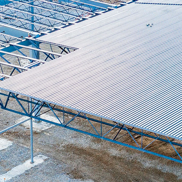
STEEL JOISTS & JOIST GIRDERS
STEEL DECK
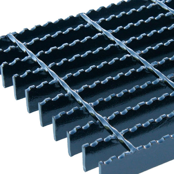
STEEL GRATING
CONTACT US
ONLINE DESIGN TOOLS
Copyright © VULCRAFT 2025. All rights reserved.