English | Français
EN | FR

Scissor-Type Joists

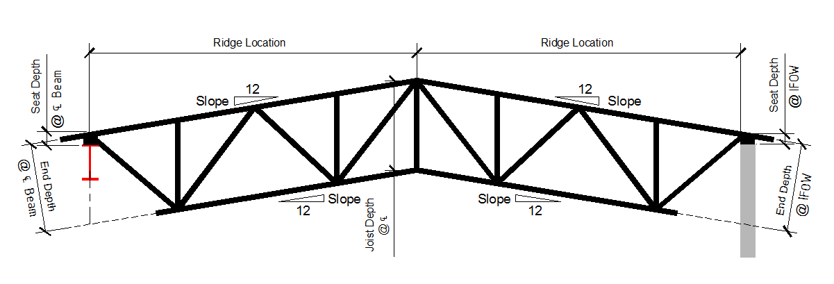
Scissor-Type Joists Have Parallel Double-Pitched Top And Bottom Chords With The Ridge At The Centerline. The Pitch Is Constant From The Bearing Point To The Ridge And Is The Same On Each Side Of The Ridge With A Modified Warren Web Configuration

1. ANALYSIS AND DESIGN PROCEDURES

This product has significant effects on the analysis of the entire structure because of horizontal force effects at the support points. These forces and horizontal deflection limitations must be defined by the specifying design professional.

2. FABRICATION PROCEDURES

These joists have double-pitched top and bottom chords, which are the only variations from Vulcraft’s standard joist fabrication procedures.

SCISSOR CHORD INFORMATION CHECKLIST

Indicating the following required information on the structural drawings will expedite the pricing and detailing of the project, resulting in fewer questions on the joist approval drawings.

  1. All dimensions indicated on the above diagram. Joist depth shall be indicated at the joist centerline.
  2. Pitch rate of the top and bottom chord on both sides of the joist.
  3. The joist designation shall be provided in a format similar to: “36LH200/100 SP” where: “36” is the depth at the joist centerline in inches, and “200” is the total uniform design load, of which “100” is live load. Loads are in plf.
  4. If design loading includes non-uniform loading, a load diagram shall be provided. This diagram should include any unbalanced loads resulting from the shape of the joist profile.
  5. Showing web layouts on structural drawings is not required unless there is a specific requirement. Unless instructed otherwise by a note on the structural drawings, Vulcraft will configure the web layout for the best economical and structural solution.

Due to the nature of a scissor chord joist, a horizontal thrust force and/or horizontal deflection will be experienced by the joist. Consequently, the bearing restraints must be considered to model the joist correctly. The design criteria resulting from the modeled bearing restraints must be noted so that they can be properly considered in the design of the joist. Contact Vulcraft with any questions.

NOTES

  1. As with all joists, self-weight shall be included in the design dead load. Alternatively, it is recommended to specify on the structural drawings that joist self-weight is to be added to the design dead load by the joist manufacturer.
  2. Bridging is per the Steel Joist Institute Standard Specifications for LH and DLH series joists. Rather than indicate the joist bridging on the structural drawings, it is acceptable to note on the plans that bridging is to be detailed by the joist supplier. In cases where the geometry of the joist results in the center of gravity being above the bearing point, additional rows of bridging will be required. Contact Vulcraft for recommendations.
  3. In the fabrication of joists, a sufficient end depth must be provided. The appropriate end depth varies with the size, shape, and loading of the joist. The end depth is the distance between the top chord and the bottom chord or the projection of the bottom chord near the center line of the support. End depth requirements increase for bottom-chord-bearing joists and sloped joists. A minimum end depth of 12” must be provided in all cases, with 18” minimum end depth in most cases and for large joists it will increase. Contact Vulcraft for end depth requirements.
  4. If joist is bottom chord bearing on either end, supply end depth.
  5. For scissor joists, the overall height of the joist must be considered due to shipping concerns. Contact Vulcraft for overall height limitations.
  6. For any questions regarding the above notes and checklist, contacting the Vulcraft engineering department is encouraged.

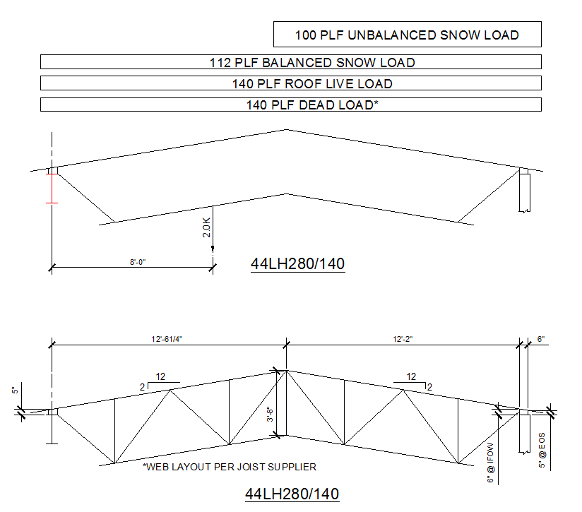
BELOW IS AN EXAMPLE OF HOW TO EFFECTIVELY SPECIFY A SCISSOR JOIST PROFILE AND LOADING DIAGRAM. DIAGRAMS SUCH AS THESE SHOULD APPEAR ON THE STRUCTURAL DRAWINGS TO EXPEDITE THE DETAILING AND APPROVAL PROCESSES.